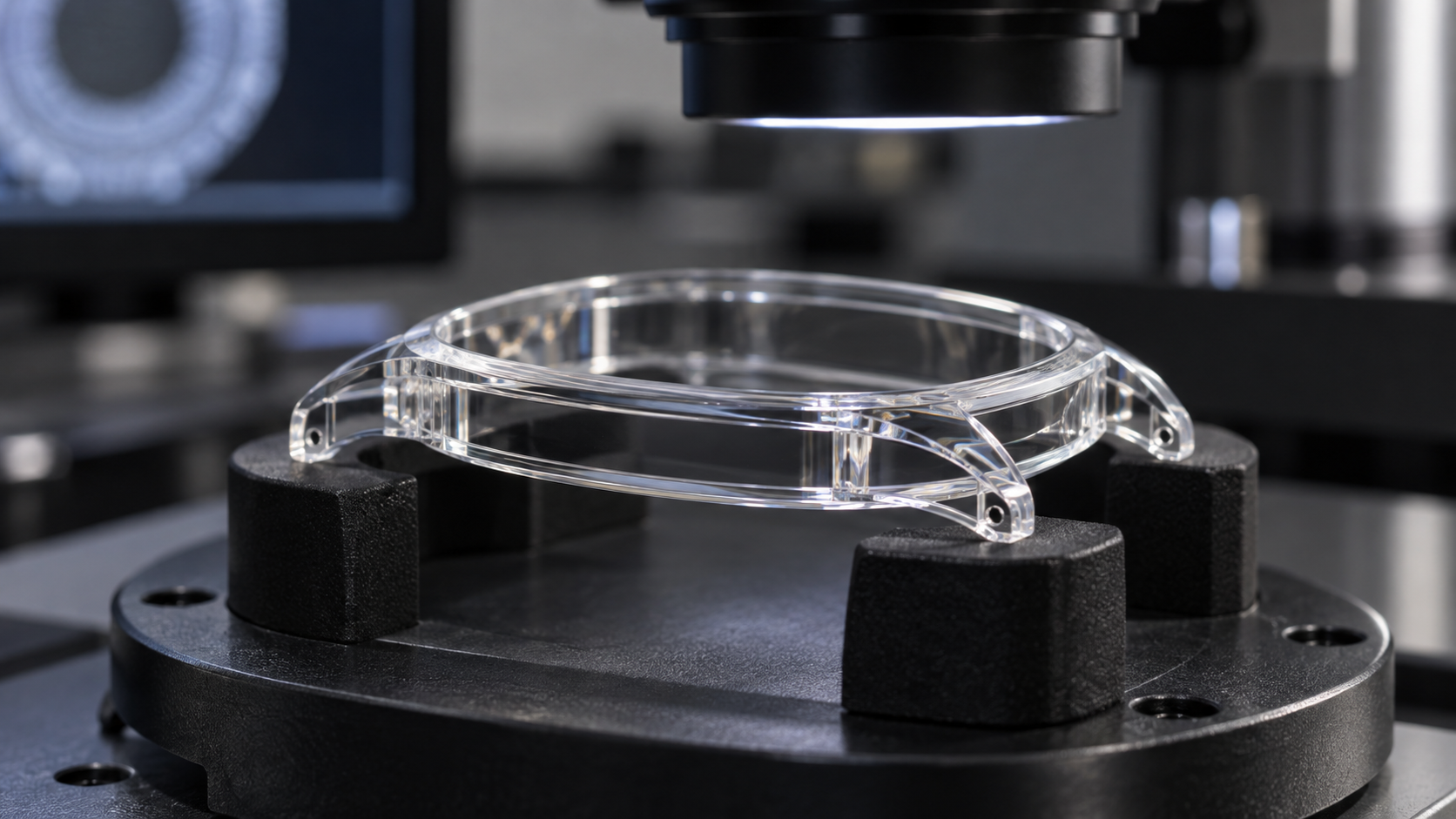
Sapphire watch cases have traditionally been associated with thick walls, large dimensions and highly limited production. That image is beginning to change. In August 2025, Bianchet presented the UltraFino Sapphire, a curved tonneau-shaped sapphire tourbillon with an overall case height of only 9.8 mm. The manufacturer also highlighted a 1.2 mm case curvature, a 3.85 mm movement and 5 ATM water resistance. The project demonstrates how far full-sapphire watch architecture has progressed.
However, a 9.8 mm watch is not the same thing as a sapphire wall measuring 9.8 mm—or proof that every sapphire case can use the same minimum wall thickness. Overall case height includes the movement space, front and rear structures, gaskets, clearances and assembly stack. Local sapphire wall thickness may vary significantly around the bezel, case middle, lugs, screw holes, crown opening and sealing surfaces.
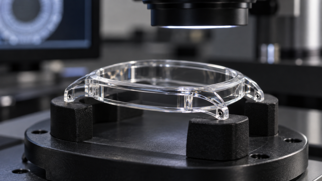
The honest answer to “How thin can a sapphire watch case be?” is therefore: there is no universal minimum. The limit depends on geometry, unsupported span, crystal orientation, machining damage, surface finish, assembly load, shock requirement, water-resistance target and acceptable production yield.
For watch brands and independent designers, the more useful question is not “What is the thinnest wall a supplier has ever made?” It is “What wall-thickness distribution gives this specific watch sufficient rigidity, fracture margin and manufacturing yield?”
Overall Case Height and Local Wall Thickness Are Different Specifications
An ultra-thin watch is a complete mechanical package. Reducing its height may require changes to the movement, hands, dial, crystal, caseback, gaskets, rotor, fasteners and movement-support structure. The sapphire case cannot be designed in isolation.
A case drawing should therefore distinguish between:
- Total assembled watch height
- Bezel thickness and crystal-support geometry
- Case-middle wall thickness
- Minimum material around screw holes and threaded inserts
- Crown and pusher opening reinforcement
- Lug-root thickness
- Gasket-land thickness and flatness
- Caseback thickness
- Minimum remaining wall after polishing
A single “minimum wall” note is rarely sufficient for a complex sapphire case. The drawing should identify local critical sections and the final thickness after all grinding, lapping and polishing operations.
This distinction becomes especially important in curved or tonneau-shaped cases. A curved shell can offer better rigidity than a flat panel of similar thickness, but transitions between the curved wall and a lug, hole or flat sealing surface may become the highest-stress locations.
Sapphire Is Hard and Stiff, but It Is Still Brittle
Synthetic sapphire is single-crystal aluminium oxide. Its Mohs hardness of 9 gives it excellent resistance to everyday scratching, and its high elastic modulus helps it resist elastic deformation. These properties make sapphire attractive for a slim, transparent watch structure.
Yet hardness, rigidity and fracture resistance describe different behaviours.
- Hardness concerns resistance to scratching or indentation.
- Rigidity concerns how much a component elastically deflects under load.
- Strength concerns the stress at which failure begins.
- Fracture toughness concerns the ability to resist the growth of an existing crack.
A thin sapphire wall may feel very rigid during normal handling but still be vulnerable to a concentrated impact at an edge or to tensile stress around a machining flaw. Unlike metal, sapphire does not provide a large plastic-deformation warning before failure.
The strength of a finished sapphire component is also flaw-sensitive. The raw crystal may have excellent intrinsic properties, but the practical case strength can be limited by scratches, edge chips, grinding damage, subsurface cracks or local stress introduced during assembly.
This is why material hardness alone cannot be used to approve an ultra-thin design.
Why Small Reductions in Thickness Matter So Much
For a simplified flat plate with the same material, span and support conditions, bending stiffness is proportional to the cube of thickness:
Bending stiffness ∝ thickness³
If thickness is reduced by 20%, the simplified bending stiffness becomes approximately 0.8³, or 51% of the original value. In other words, a relatively modest thickness reduction can nearly halve resistance to bending.
A real watch case is not a simple flat plate. It includes curves, ribs, holes, lugs, stepped surfaces and multiple assembled components. Nevertheless, the cubic relationship explains why the final fractions of a millimetre can be so difficult to remove. The visual difference may appear small while the mechanical effect is substantial.
Deflection also matters even when the sapphire does not fracture. Excessive movement can change gasket compression, allow contact with the movement, alter crown or pusher alignment, or create local loading against a screw or metal insert.
Ultra-thin design must therefore control both maximum stress and maximum deflection.
The Main Factors That Determine Minimum Wall Thickness
Unsupported Span
A broad transparent wall with little support generally needs more thickness than a narrow wall located between structural ribs. Diameter, case width and the distance between fasteners all influence bending behaviour.
This is one reason why a minimum thickness copied from a smaller watch may be unsafe when applied to a larger case.
Curvature and Shell Geometry
Controlled curvature can improve structural efficiency by distributing load through a shell rather than a flat plate. However, curvature also makes machining and polishing more difficult. Thickness must remain consistent through the curved section, and tangent transitions should avoid abrupt changes that create stress concentration.
Lugs and Strap Loads
The lug root is one of the most critical regions in a full-sapphire case. Strap forces introduce bending and torsion, while accidental impacts can apply leverage through the spring bar or attachment system. A thin case middle does not mean the lug root should have the same wall thickness.
Generous transition radii, sufficient local material and a controlled load path are usually more important here than achieving uniform visual thinness.
Screw Holes, Inserts and Counterbores
Every hole removes load-carrying material and creates a geometric discontinuity. Counterbores, sharp internal corners and closely spaced holes can further increase local stress.
Minimum remaining material around each hole should be evaluated after all tolerances and polishing allowances are applied. Fastener torque must also be controlled so the sapphire is compressed predictably rather than loaded by an uneven point contact.
Crown and Pusher Openings
Crown tubes and pushers interrupt the case wall and can introduce load during operation. A very thin local section may crack during assembly even if it survives machining. The interface may require additional wall thickness, a separate metal component or a geometry that spreads the load over a larger area.
Gasket Compression and Water Resistance
A sealing system needs enough stiffness to maintain controlled gasket compression. If a thin sapphire flange deflects under screw preload or pressure, compression may become uneven. Increasing torque is not a safe correction because it can increase stress around the fasteners and edges.
The sealing target, gasket material, groove geometry, fastener pattern and tightening sequence must be designed as one system.
Crystal Orientation
Sapphire is anisotropic. Its machining response and fracture behaviour can vary with crystallographic orientation and loading direction. Orientation should therefore be controlled from the raw blank through final inspection, especially when thin sections, holes or narrow lugs are involved.
Surface and Subsurface Condition
A surface can appear optically smooth while retaining subsurface damage from earlier grinding. NIST research on single-crystal sapphire found that specimens with similar measured surface roughness could still have substantially different strength because damage remained beneath the polished surface.
For thin watch cases, surface roughness is therefore only one quality indicator. The complete machining history and the depth of damaged material removed during finishing also matter.
Thin-Wall Design Should Use a Thickness Map
The most practical sapphire case is not always one with uniform wall thickness. A controlled thickness map can place material where it contributes most to performance.
For example:
- Transparent side panels may be comparatively thin when their span is short and their edges are well supported.
- Lug roots can be locally thicker to carry strap loads.
- Screw bosses may need additional radial material.
- Gasket lands may require more thickness to maintain flatness.
- Crown openings can use a reinforced local transition.
- Decorative recesses should avoid reducing already critical sections.
The thickness map should show nominal and minimum-after-polishing dimensions. It should also identify cosmetic surfaces where excessive material removal is not permitted.
Because sapphire is transparent, structural reinforcement cannot always be hidden. In many designs, the solution is to turn reinforcement into part of the visual language: a curved rib, a stepped edge, a visible gasket line or a metal movement-support frame can become an intentional design feature.
Rigidity Must Be Evaluated at Assembly Level
Testing an individual sapphire component does not fully represent the behaviour of a complete watch. The bezel, case middle, caseback, gaskets, screws, movement ring and movement all interact.
A finite-element model should include realistic contacts and assembly preload rather than treating the case as a single unloaded shell. Useful load cases may include:
- Screw tightening and gasket compression
- External pressure associated with the target water-resistance rating
- Crown or pusher operating force
- Strap pull and torsion at the lugs
- Wrist impact and representative drop orientations
- Thermal cycling across the intended service range
The model should examine both tensile stress and deformation. It should also include tolerance extremes, because the thinnest permitted wall combined with the highest permitted gasket compression may be more critical than the nominal design.
Simulation is most valuable for comparing design options and locating risk. It should not be presented as a substitute for prototype tests, especially when brittle-material strength depends on the actual manufactured flaw population.
Shock Resistance Is Controlled by the Load Path
A scratch-resistant case is not automatically impact-resistant. During a drop or wrist impact, energy travels through the point of contact, sapphire shell, screws, gasket system, movement support and strap attachments.
Several details can improve shock performance:
- Rounded external transitions instead of sharp impact-sensitive edges
- Sufficient material around lugs and fastening points
- Gaskets or support elements that prevent hard component-to-component contact
- Controlled clearances between the movement and sapphire walls
- Fasteners that maintain preload without producing concentrated stress
- A movement-support structure that distributes load rather than transferring it into one thin wall
Drop direction is important. A case may perform well when loaded through the broad bezel but remain vulnerable at a lug tip, crown side or caseback edge. Qualification should therefore include multiple orientations selected from realistic failure risks.
If a movement is advertised with a high shock rating, that rating should not automatically be assigned to the complete sapphire watch. Movement testing and complete-case testing are different evaluations.
Why Polishing Yield Becomes Critical as Walls Become Thinner
Sapphire polishing performs two jobs. It creates optical clarity, and it removes damage left by earlier machining. In an ultra-thin case, these goals must be achieved without losing dimensional control.
Deflection During Polishing
A thin wall may flex under fixture or polishing pressure. Even small deflection can create non-uniform removal, waviness or local over-polishing. Fixtures should support the part without creating concentrated contact against fragile edges.
Edge Roll and Geometry Loss
Polishing naturally tends to round exposed edges. On a thin case, edge roll can reduce the local wall below specification or change the fit with a gasket, bezel or caseback. Critical edges need protected polishing strategies and sufficient finishing allowance.
Uneven Removal Around Curves
Curved tonneau and asymmetric cases do not present a uniform contact condition to a polishing tool. Convex regions may remove faster, while internal transitions may remain difficult to access. The supplier must balance optical uniformity against profile accuracy.
Damage That Survives a Beautiful Surface
A low roughness value does not prove that all subsurface damage has been removed. The polishing route must be matched to the damage depth created during grinding. Attempting to minimize polishing time may leave strength-limiting flaws; excessive polishing may destroy the intended dimensions.
Handling Losses Late in Production
The case becomes most valuable after long machining and polishing cycles, yet the final thin component is also more sensitive to edge contact during cleaning, measurement and assembly. Dedicated trays, protected fixtures and stage-by-stage inspection become part of yield control.
Polishing yield should therefore be considered during design, not treated only as a supplier’s production problem.
Designing the Manufacturing Sequence
A robust process route for a thin sapphire case may include:
- Incoming blank inspection and crystal-orientation confirmation.
- Rough machining with sufficient stock retained around critical walls.
- Intermediate dimensional measurement and inspection for edge damage.
- Semi-finishing of the case geometry and functional interfaces.
- Controlled lapping and damage-removal operations.
- Optical polishing with fixtures designed for the thin-wall geometry.
- Final non-contact thickness mapping and profile measurement.
- Detailed visual and stress-related optical inspection.
- Controlled assembly using specified gasket, screw and torque conditions.
- Pressure, functional and shock validation according to the watch specification.
Machining every surface to its final dimension before evaluating polishing behaviour can be risky. Prototype parts should be used to establish actual removal allowances for each visible and functional zone.
Inspection Requirements for Ultra-Thin Sapphire Cases
Inspection should verify more than one minimum thickness point. A complete plan may include:
- Non-contact wall-thickness mapping across critical sections
- Three-dimensional profile measurement of curved exterior and interior surfaces
- Position and diameter of holes, counterbores and gasket features
- Flatness of sealing lands
- Edge-chip inspection under controlled lighting and magnification
- Bright-field, dark-field and transmitted-light inspection
- Cross-polarized examination for stress-related optical patterns where applicable
- Cosmetic inspection from every normal viewing direction
- Dimensional reinspection after assembly preload is applied
- Water-resistance or pressure testing of the assembled case
- Representative shock, strap-load and environmental validation
Inspection conditions should be defined in the drawing or quality agreement. Statements such as “no deformation,” “no chips” or “perfect transparency” are difficult to enforce unless measurement method, magnification, lighting and acceptance limits are specified.
Prototype Strategy and Production Yield
The first prototype should not be expected to prove the ultimate minimum wall thickness immediately. A staged development program is usually more efficient.
The initial case can retain additional material in the highest-risk areas. Inspection and test results can then guide controlled reductions. Representative curved coupons, lug sections and screw-hole geometries may be used to qualify grinding and polishing before a complete case is produced.
A useful validation program may include:
- First-article dimensional inspection
- Gasket-compression and torque trials
- Pressure testing at the specified level
- Multi-orientation drop or impact evaluation
- Strap pull and lug-load testing
- Thermal cycling of the assembled material stack
- Destructive testing of designated development samples
- Review of defects and yield across the pilot lot
The objective is not merely to produce one successful showpiece. It is to establish a process window that can repeatedly deliver acceptable parts at the intended production quantity.
What to Include in an RFQ for a Thin Sapphire Watch Case
To evaluate feasibility, a supplier should receive enough information to review the entire structure. A useful RFQ package includes:
- Native 3D CAD and controlled 2D drawings
- Target overall watch dimensions
- A local wall-thickness map rather than only one minimum value
- Sapphire colour, orientation and optical requirements
- Movement envelope and assembly clearances
- Bezel, caseback, gasket, crown and pusher interfaces
- Screw materials, quantities, locations and target torque
- Lug and strap-attachment design
- Water-resistance and shock requirements
- Polished, frosted and hidden surface definitions
- Cosmetic and edge-quality acceptance criteria
- Prototype and production quantities
- Required dimensional reports and validation tests
If the design is still preliminary, the 3D model can be submitted for a manufacturability review before final tolerances are frozen. This makes it easier to strengthen local features without changing the overall appearance of the watch.
Conclusion
Recent ultra-thin sapphire watches show that a full transparent case no longer needs to be excessively bulky. Achieving a case under 10 mm in total height is now possible in a carefully integrated design. It does not, however, create a universal minimum wall-thickness rule.
The practical limit is determined by the entire system: case size, curvature, unsupported span, lugs, holes, gaskets, assembly preload, crystal orientation, machining damage, polishing allowance and qualification requirements. A thin wall that works in one location may be unsuitable beside a screw hole or at a lug root.
For most custom projects, the best route is to develop a local thickness map, model realistic assembly loads, prototype the most vulnerable features and validate the complete watch case after polishing and assembly. The goal should be the thinnest structure that can be manufactured repeatedly—not simply the thinnest isolated part that survives once.