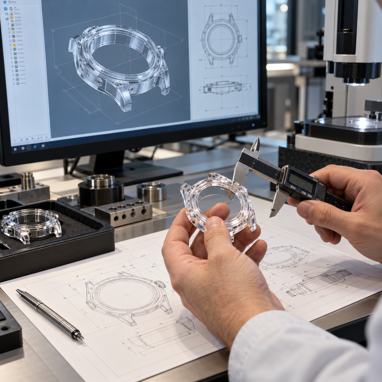
A STEP file can show the shape of a sapphire watch case.
It does not automatically define how that case should be manufactured, inspected or assembled.
For a simple visual prototype, a 3D model may provide enough information to begin a feasibility discussion. For a production sapphire case, however, the manufacturer also needs to understand which surfaces are functionally critical, which dimensions control assembly, how the part should be located during inspection and which tolerances must remain stable after grinding and polishing.
This becomes particularly important with sapphire.
Unlike stainless steel or titanium, synthetic sapphire is a hard and brittle crystal. Complex cases typically require several stages of grinding, precision machining, hole processing, fine finishing, polishing and inspection. Each stage can affect the final geometry, and polishing itself removes material.
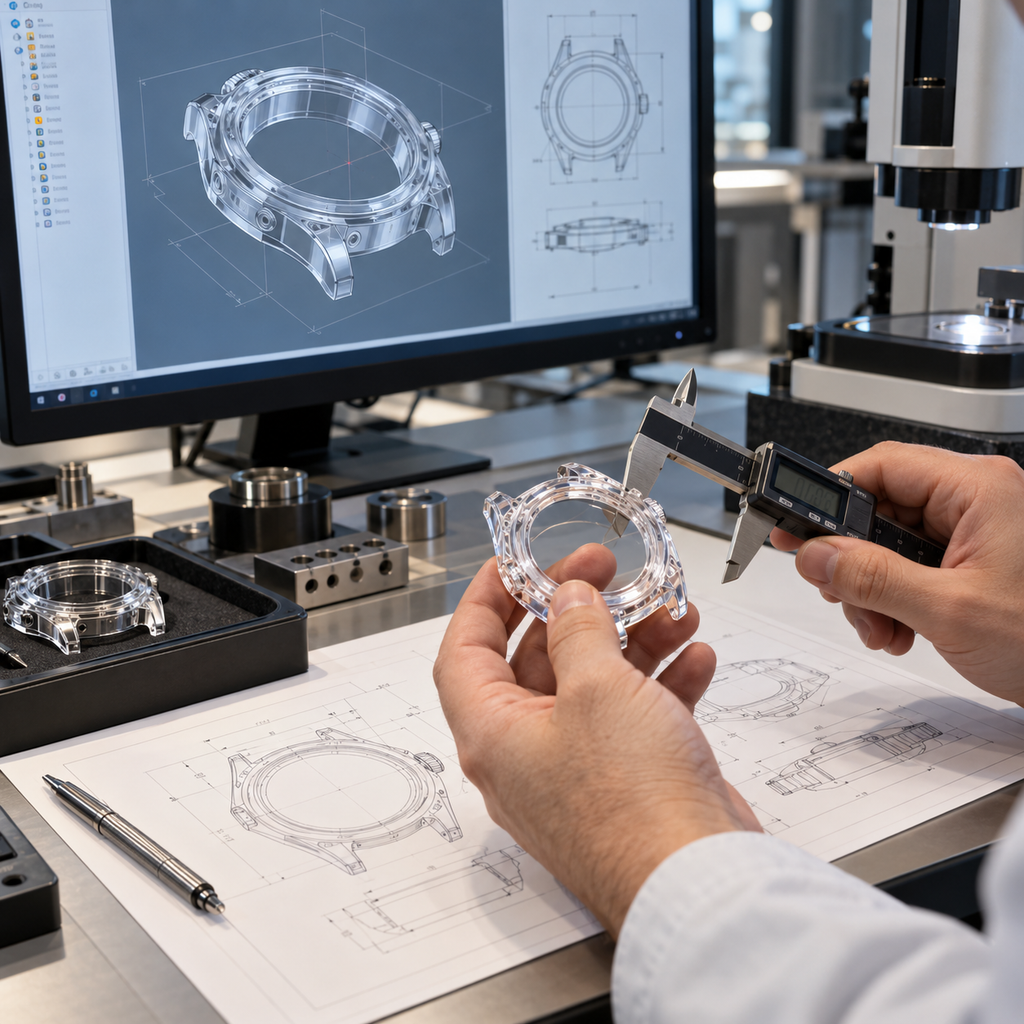
For this reason, turning a STEP file into a production-ready sapphire watch case is not simply a CNC programming task.
It is a process of translating design intent into measurable manufacturing requirements.
The critical tools include:
- Datum design
- GD&T
- Functional dimensions
- Tolerance stack-up analysis
- Process allowances
- Intermediate inspection
- First Article Inspection
- Assembly verification
Why a STEP File Alone Is Usually Not Enough
A STEP model is extremely useful.
It can define:
- Overall case geometry
- Curved surfaces
- Lug shape
- Internal cavities
- Crown guards
- Bezel geometry
- Screw locations
- Caseback interfaces
It also allows the manufacturer to evaluate tool access, machining direction and polishing accessibility.
But a STEP file does not always clearly communicate which dimensions are most important.
For example, imagine a sapphire watch case with:
- An internal movement cavity
- Four caseback screw holes
- A crown opening
- A gasket seat
- Integrated lugs
- A bezel interface
The 3D model defines where these features are located.
It may not tell the manufacturer whether the crown-hole position should be controlled primarily relative to:
- The external case profile
- The movement centerline
- The caseback plane
- The movement seat
Those are different functional relationships.
A production drawing should communicate them.
The 2D Drawing Still Matters
Modern manufacturing increasingly uses 3D CAD data, but a controlled 2D engineering drawing remains extremely useful for sapphire projects.
The drawing can identify:
- Critical dimensions
- Datums
- Position tolerances
- Flatness
- Parallelism
- Perpendicularity
- Profile requirements
- Hole tolerances
- Surface finish requirements
- Polished areas
- Cosmetic zones
- Edge radii
- Special inspection requirements
ASME Y14.5 provides a standardized language for geometric dimensioning and tolerancing so that design, manufacturing and inspection teams can interpret functional requirements consistently. The currently effective ASME edition is Y14.5-2018, reaffirmed in 2024.
For a sapphire case project, the objective is not to fill the drawing with as many GD&T symbols as possible.
The objective is to identify the geometric relationships that actually control fit, function and appearance.
What Is a Datum?
A datum is a theoretically exact reference used to establish the coordinate system from which other features are controlled.
In practical inspection, physical surfaces or features on the component are used to establish the datum reference framework.
For a sapphire watch case, a carefully selected datum system can make the difference between meaningful inspection data and a long measurement report that does not describe how the part will actually assemble.
A typical case may use a three-level datum strategy:
Datum A – Primary reference plane
For example:
- Caseback mounting plane
- Movement support plane
- Bezel seating plane
Datum B – Secondary reference
For example:
- Central cylindrical axis
- Internal movement cavity
- Defined side reference
Datum C – Clocking or orientation reference
For example:
- Crown-hole centerline
- Lug centerline
- Locating notch
- Defined case side
The correct choices depend on the case architecture.
There is no universal datum scheme for every sapphire watch case.
Choose Datums Based on Function, Not Convenience
One common mistake is selecting a datum simply because it is easy to measure.
A large polished exterior surface may be convenient for inspection, but it may not be the most important functional reference.
For example, consider the relationship between:
- Movement position
- Crown stem
- Crown hole
- Dial
- Caseback
- Bezel
If the movement location controls the crown stem alignment, then the crown-hole position should normally be evaluated relative to the functional movement reference system.
If it is measured only relative to the outside decorative contour, the case could pass inspection but still create an assembly problem.
The best datum strategy tries to reproduce how the part actually functions in the final watch.
A Typical Datum Example
Consider a monobloc sapphire case.
A possible inspection concept might use:
Datum A: Caseback Interface
The lower functional plane establishes the vertical reference.
This may influence:
- Caseback seating
- Overall case height
- Movement position
- Gasket compression
Datum B: Movement Cavity Axis
The internal cavity establishes the case center.
This can control:
- Bezel concentricity
- Dial position
- Crystal relationship
- Caseback relationship
Datum C: Crown Axis or Lug Centerline
A third datum establishes rotational orientation.
This can control:
- Crown-hole position
- Pusher locations
- Lug symmetry
- Screw-hole pattern
The actual drawing may use another system, but the principle is important:
The datum framework should reflect assembly logic.
Why GD&T Is Useful for Sapphire Cases
Traditional ± dimensions can work for simple parts.
But complex watch cases contain relationships that are difficult to describe efficiently using only coordinate dimensions.
For example, GD&T can help control:
- Position
- Profile
- Flatness
- Parallelism
- Perpendicularity
- Concentric functional relationships
ASME describes GD&T as a standardized method for communicating the form, fit and function intended by the designer.
This is especially useful when a sapphire case contains several mating components.
Position Tolerance for Holes
A sapphire watch case may include holes for:
- Caseback screws
- Bezel screws
- Crown tubes
- Pushers
- Spring bars
- Strap attachments
- Decorative fasteners
Specifying only the hole diameter is not enough.
Consider:
Ø1.50 ±0.02 mm
This controls size.
It does not fully control where the hole axis is located.
For assembly, the manufacturer may also need to control the hole position relative to the datum system.
A positional requirement helps define the acceptable region in which the hole axis can exist.
This becomes important when a metal component must pass through or align with the sapphire.
Crown-Hole Position Is Particularly Important
The crown interface is one of the most functionally sensitive areas of a watch case.
The crown-hole location must coordinate with:
- Movement stem height
- Movement position
- Crown tube
- External crown geometry
- Gasket system
Even a visually small position error can affect stem alignment.
If the hole axis is not properly related to the movement location, assembly may require force or create uneven loading.
With metal, a small amount of adjustment may sometimes be possible.
Sapphire offers much less flexibility.
The geometry should therefore be correct before assembly.
Profile Tolerance Can Be Useful for Complex Surfaces
Modern sapphire watch cases frequently use:
- Tonneau shapes
- Curved sidewalls
- Organic surfaces
- Integrated lugs
- Compound radii
- Sculpted crown guards
Trying to dimension every point of such a surface individually can make the drawing difficult to interpret.
A profile tolerance can instead define how closely the actual manufactured surface must remain to the theoretically exact CAD geometry.
ASME Y14.5 specifically supports profile controls for defining complex surfaces and their relationship to datum systems.
This can be particularly useful when the design includes freeform sapphire geometry.
Flatness Matters at Functional Interfaces
Not every polished surface needs a very tight flatness requirement.
Functional sealing and assembly surfaces are different.
Potential flatness-critical areas include:
- Caseback seating surface
- Gasket interface
- Bezel interface
- Movement support surface
- Crystal seating surface
If these surfaces are excessively distorted, problems may include:
- Uneven gasket compression
- Assembly gaps
- Rocking between components
- Localized contact pressure
- Cosmetic gaps
The required flatness should match the actual function.
Applying extremely tight flatness to every surface only increases cost without necessarily improving the watch.
Parallelism Can Affect the Entire Case Assembly
Suppose a sapphire middle case contains:
- A bezel seating surface
- A caseback seating surface
If these surfaces are not sufficiently parallel, the finished assembly may show:
- Uneven overall height
- Uneven gasket compression
- Visual asymmetry
- Misalignment with the movement
Parallelism can therefore be more meaningful than simply giving independent height dimensions from unrelated points.
Perpendicularity Is Important Around Crown and Pusher Features
A hole can be in the correct nominal location but still have an incorrect axis angle.
This is especially important for:
- Crown tubes
- Pushers
- Screw holes
- Strap pin holes
If a crown opening is not properly oriented relative to the case reference system, a crown tube may enter at an angle.
This can affect:
- Assembly
- Stem alignment
- Gasket behavior
- External appearance
Therefore, axis orientation may need to be controlled in addition to position.
Do Not Apply Metal Tolerances Blindly to Sapphire
A sapphire case drawing is sometimes derived directly from an existing titanium or stainless-steel case.
The designer may copy all the original tolerances.
That can create problems.
Sapphire is processed differently.
Complex components commonly pass through multiple stages of grinding, precision machining and polishing, and tight internal geometries can also create tool-access or edge-risk challenges.
For each tolerance, the engineering team should ask:
Does this tolerance actually affect function?
If yes, it should be controlled appropriately.
If not, unnecessarily tight tolerances may:
- Increase machining time
- Increase inspection time
- Reduce yield
- Increase polishing difficulty
- Increase scrap risk
- Increase unit cost
The goal is not the smallest possible tolerance.
The goal is the right tolerance in the right place.
Tolerance Stack-Up: One of the Most Important Issues
A watch is an assembly.
The location of one component often depends on several dimensions.
Consider the crown stem.
Its final alignment may depend on:
- Caseback reference
- Movement holder thickness
- Movement position
- Sapphire cavity position
- Crown-hole height
- Crown tube geometry
Each dimension has its own tolerance.
When these variations combine, the final crown-stem alignment may move away from nominal.
This is tolerance stack-up.
A Simple Tolerance Stack Example
Imagine three dimensions determine the vertical position of a functional interface:
A = 2.00 ±0.03 mm
B = 3.00 ±0.02 mm
C = 1.50 ±0.03 mm
Nominal total:
6.50 mm
Using a simple worst-case approach, the combined variation could reach:
±0.08 mm
Each individual tolerance looks small.
The assembly variation is much larger.
This is why the engineering team should not evaluate dimensions only one at a time.
Typical Sapphire Watch Case Tolerance Chains
Important stack-ups can occur between:
Movement and Crown
Movement seat
→ movement centerline
→ crown hole
→ crown tube
→ crown
Case and Caseback
Caseback seat
→ gasket
→ caseback thickness
→ screw preload
→ assembled height
Bezel and Middle Case
Bezel interface
→ gasket
→ sapphire middle case
→ screw location
Strap or Bracelet
Lug position
→ lug spacing
→ pin hole
→ end link
→ bracelet centerline
A small deviation in several components can become visually or functionally significant after assembly.
Avoid Duplicate Dimension Chains
Another drawing problem occurs when the same geometry is controlled in multiple conflicting ways.
For example:
A designer may specify three sequential dimensions and also specify the overall dimension.
If all four dimensions have independent tolerances, they can mathematically conflict.
A better strategy is to identify the functional relationship that really matters and dimension from controlled references.
This makes manufacturing and inspection easier.
Sapphire Polishing Must Be Included in the Tolerance Strategy
One of the most important differences between a CAD model and a finished sapphire case is polishing.
Polishing removes material.
Therefore, dimensions measured immediately after precision grinding may differ from dimensions after final polishing.
Your existing sapphire-case manufacturing guidance already emphasizes that polishing can alter:
- Wall thickness
- Flatness
- Transition geometry
- Movement pockets
- Caseback interfaces
- Gasket seats
and therefore polishing allowance must be considered during manufacturing planning.
This means the manufacturer may intentionally machine certain regions slightly away from final size before polishing.
Not Every Dimension Should Be Finished at the Same Stage
A useful manufacturing plan may divide features into groups.
Pre-Polish Geometry
Features created during rough and fine machining.
Polish-Sensitive Geometry
Features where dimensional change during polishing must be predicted.
Final Functional Geometry
Features that may require final correction or verification after major polishing stages.
The correct process depends on the case design.
The important point is that inspection timing must correspond to manufacturing timing.
Intermediate Inspection Reduces Scrap Risk
A complex sapphire case becomes more valuable as it progresses through production.
After rough machining, relatively little processing value has been added.
After precision machining, multiple grinding stages and optical polishing, the component represents substantially more time and cost.
Therefore, waiting until the final inspection to discover a major dimensional problem is inefficient.
A staged inspection plan can include:
After Rough Machining
Check:
- Overall envelope
- Wall thickness
- Major cavities
- Material defects
After Precision Machining
Check:
- Hole positions
- Movement cavity
- Screw pattern
- Critical interfaces
- Remaining polishing allowance
After Fine Grinding
Check:
- Critical dimensions
- Geometry
- Edge condition
After Final Polishing
Check:
- Final dimensional requirements
- Optical clarity
- Surface defects
- Edge quality
- Assembly interfaces
This approach helps detect problems before additional expensive work is added.
What Is First Article Inspection?
First Article Inspection, or FAI, is a structured verification that the first production-representative component conforms to the agreed engineering requirements.
The concept is widely formalized in industries such as aerospace. SAE AS9102C, revised in 2023, establishes requirements for performing and documenting First Article Inspection in aerospace manufacturing.
A luxury watch case does not automatically need to follow aerospace AS9102 documentation.
However, the underlying principle is very useful:
Before releasing a new component into batch production, verify that the manufacturing process can produce a part matching the complete approved definition.
First Article Inspection for a Sapphire Watch Case
For a sapphire project, an FAI package can be adapted to the needs of the watch brand.
It may include:
Dimensional Inspection
- Overall case dimensions
- Case height
- Movement cavity
- Lug spacing
- Crown-hole position
- Screw-hole positions
- Bezel interface
- Caseback interface
- Wall thickness
- Critical radii
GD&T Inspection
Where specified:
- Flatness
- Parallelism
- Perpendicularity
- Position
- Profile
Cosmetic Inspection
- Scratches
- Pits
- Chipping
- Haze
- Polishing marks
- Internal inclusions
- Edge defects
Optical Inspection
- Transparency
- Distortion
- Surface consistency
- Colored sapphire consistency where applicable
Assembly Inspection
- Movement fit
- Crown alignment
- Caseback fit
- Bezel fit
- Screw alignment
- Gasket interface
- Strap or bracelet fit
The purpose is not just to prove that individual numbers meet the drawing.
The first article must demonstrate that the component actually works as part of the watch.
Balloon the Drawing for FAI
A practical inspection method is to create a ballooned drawing.
Each measurable characteristic receives an identification number.
For example:
- Overall width
- Case height
- Movement cavity diameter
- Crown-hole diameter
- Crown-hole position
- Lug spacing
- Caseback flatness
- Screw-hole position
- Bezel interface
- Surface finish requirement
The inspection report then records the measured result against each characteristic.
This creates clear traceability between:
drawing requirement → inspection result → acceptance
It also prevents important dimensions from being accidentally skipped.
STEP File, Drawing and Inspection Report Must Use the Same Revision
Revision control is essential.
A common development problem is that several files circulate at the same time:
- STEP V3
- Drawing V4
- Updated crown location by email
- Modified caseback dimensions in another file
The manufacturer may machine from one revision while the customer inspects against another.
This creates unnecessary disputes.
Before prototype or batch production begins, the project should identify:
- STEP revision
- 2D drawing revision
- Color specification revision
- Surface-finish specification
- Assembly component revision
These should form one controlled production package.
First Article Does Not Mean the First Rough Prototype
An early prototype may be manufactured primarily to understand:
- Overall appearance
- Manufacturing feasibility
- Wall thickness
- Polishing accessibility
It may not use the final process.
A First Article should normally be more representative of the intended production route.
Ideally, it uses:
- Production-intent material
- Production-intent machining
- Production-intent polishing
- Production fixtures
- Production inspection method
Otherwise, approving the first article provides limited evidence about future batch consistency.
Measure the Part After Final Polishing
This is particularly important for sapphire.
If critical dimensions are inspected only before optical polishing, the inspection report may not describe the part the customer actually receives.
Final inspection should therefore confirm the dimensions most sensitive to material removal.
Typical examples include:
- Gasket seats
- Caseback interfaces
- Bezel interfaces
- Overall thickness
- Lug geometry
- Critical flat surfaces
The need for post-polish dimensional inspection follows directly from the fact that polishing modifies the sapphire geometry.
Use the Right Measurement Method
Different features require different inspection tools.
Depending on the geometry and tolerance, a sapphire case may be inspected using:
- CMM
- Optical measurement systems
- Vision measuring machines
- Height measurement
- Micrometers
- Bore measurement
- Surface profilometry
- Optical comparators
- Custom gauges
No single measurement method is ideal for every feature.
For example, a polished transparent edge may be difficult to detect reliably using a measurement method developed for opaque metal.
The inspection method itself should therefore be validated for the actual sapphire component.
Cosmetic Zones Should Also Be Defined
Dimensions are only one part of sapphire quality.
Because the case is transparent, cosmetic defects can be visible from multiple directions.
The drawing or quality specification can divide surfaces into categories such as:
Zone A – Primary visible optical surface
Very strict requirements.
Zone B – Secondary visible surface
Controlled cosmetic requirements.
Zone C – Functional internal area
Dimensional performance may be more important than optical appearance.
This helps prevent ambiguous statements such as:
“Surface must be perfect.”
A measurable or visually referenced acceptance system is much more effective.
Golden Sample and First Article Can Work Together
Once the first production-representative sapphire case has been approved, it can become a reference sample.
A golden sample can help define:
- Optical clarity
- Edge appearance
- Polishing quality
- Colored sapphire appearance
- Acceptable internal reflections
- Assembly fit
Future production batches can then be compared with both:
the engineering drawing
and
the approved physical sample.
The drawing controls measurable engineering requirements.
The golden sample helps control visual expectations.
When Should a New First Article Be Required?
A new or partial first article review may be appropriate after a meaningful change such as:
- Major geometry revision
- New crown position
- Changed movement cavity
- New sapphire blank route
- Major machining-process change
- New fixture
- Significant polishing-process change
- Change to a critical mating component
The purpose is not to create unnecessary paperwork.
It is to verify that a meaningful change has not introduced a new assembly or quality problem.
A Recommended Development Workflow
A practical sapphire watch-case development sequence may look like this:
1. Receive Project Data
Customer supplies:
- STEP file
- 2D drawing
- Movement information
- Crown information
- Caseback design
- Bezel design
- Target sapphire color
- Target quantity
2. DFM Review
Evaluate:
- Tool accessibility
- Internal radii
- Thin walls
- Hole geometry
- Edge risk
- Polishing access
- Critical tolerances
Complex sapphire geometry requires this early review because tool access, wall transitions, holes and polishing strategy can determine whether a CAD design is realistically manufacturable.
3. Establish Functional Datums
Define which features control:
- Movement location
- Crown alignment
- Bezel position
- Caseback position
- Lug orientation
4. Review GD&T
Confirm:
- Position controls
- Profile controls
- Flatness
- Parallelism
- Perpendicularity
5. Perform Tolerance Stack Analysis
Evaluate critical assembly chains.
6. Define Process Allowances
Account for:
- Grinding
- Fine finishing
- Polishing
7. Produce Prototype
Manufacture initial parts.
8. Intermediate Inspection
Verify critical geometry before expensive final polishing.
9. Final Polish
Complete optical finishing.
10. Final Dimensional Inspection
Confirm production dimensions.
11. Trial Assembly
Check mating components.
12. First Article Approval
Approve:
- Dimensions
- Appearance
- Optical quality
- Assembly performance
13. Freeze Production Revision
Lock:
- STEP file
- 2D drawing
- Material specification
- Finish
- Inspection standard
14. Batch Production
Produce future components against the same controlled definition.
What Should a Brand Send for Technical Review?
For the most efficient engineering evaluation, a sapphire watch-case RFQ should include:
CAD Data
- STEP file
- 2D drawing
- Drawing revision
Functional Information
- Movement model or envelope
- Movement stem height
- Crown and crown-tube geometry
- Caseback design
- Bezel interface
- Gasket arrangement
- Strap or bracelet interface
Sapphire Requirements
- Clear or colored sapphire
- Crystal requirements
- Surface finish
- Polished and frosted regions
Quality Requirements
- Critical dimensions
- GD&T
- Cosmetic zones
- Inspection requirements
- Reference sample if available
Commercial Information
- Prototype quantity
- First production quantity
- Estimated annual requirement
This allows the manufacturer to evaluate the part as an assembly component rather than simply quote a piece of sapphire with a complicated shape.
The Most Important Question Is Not “Can You Machine This?”
Many complex sapphire watch-case designs can eventually be machined.
That does not mean they are ready for reliable batch production.
The more important questions are:
- What surfaces define the functional coordinate system?
- Which dimensions control assembly?
- Which tolerances accumulate?
- Which features change during polishing?
- How will each critical requirement be measured?
- What exactly must the first article prove?
- How will the approved configuration be maintained in production?
Answering these questions before manufacturing begins significantly reduces the risk of discovering problems after an expensive sapphire component has already been fully polished.
From CAD Geometry to Controlled Production
A STEP file describes geometry.
A production-ready sapphire watch case requires much more.
It requires a controlled relationship between:
3D CAD
+
2D engineering drawing
+
datum structure
+
GD&T
+
tolerance stack-up
+
machining allowances
+
inspection method
+
assembly verification
+
first article approval
This becomes increasingly important as sapphire cases become more complex.
Integrated lugs, curved walls, thin structures, crown guards, multiple screw patterns and precision movement interfaces all increase the number of dimensions that interact with each other.
For luxury watch brands and independent watchmakers, involving the sapphire manufacturer before the drawing is frozen can therefore save considerable development time.
Rather than manufacturing the STEP file exactly as supplied and discovering assembly problems afterward, the project can first identify critical datums, realistic tolerances, polishing allowances and inspection requirements.
The result is not simply a sapphire component that matches a CAD model.
It is a sapphire watch case that can be measured, assembled and reproduced consistently from prototype to batch production.
Developing a custom sapphire watch case?
Send your STEP file, 2D drawing, movement information, mating-component drawings and target quantity for a manufacturability and tolerance review before prototype production.